

How To Make A Fm Radio
How to DIY your FM Radio Antenna|Homemade FM Antenna Nuts&Tutorials
Date:2020/11/17 16:51:43 Hits:
"Is information technology too expensive to purchase FM antennas from Wal-Mart, Alibaba, Amazon? Why not DIY a simple FM antenna? This DIY FM antenna production and installation tutorial article provides the most consummate DIY FM radio antenna tutorial method. Y'all tin learn how to DIY a proficient radio FM antenna pace by step through this chapter. We volition too provide yous with a adding method of the length of a DIY FM antenna and the tools and materials you need to set when yous want to make a homemade antenna, before installing DIY FM radio antenna, when installing DIY FM radio antenna, and all the matters needing attention later installing DIY FM radio antenna, let's have a wait! ----- FMUSER "
Content
i) Before DIY FM Radio Antenna
ii) How to Make An FM Dipole Antenna Design?
3) Why Do You Need To Brand An FM Antenna From Speaker Wire?
iv) Simple DIY FM Dipole Antenna Design
5) DIY FM Antenna Method for Beginners
half-dozen) DIY FM Antenna Method ( Advanced Version)
M1 Using a Coaxial Cable
M2 Using Speaker Wire
vii) DIY FM Antenna Method In Conclusion
8) How To Make A VHF FM Folded Dipole Antenna?
9) How to Brand a Uncomplicated Antenna to Improve the Reception of an FM Radio Receiver
10) How to Get More than Channels With A Homemade Antenna?
eleven) How to Build a Bootleg Radio That Actually Works
▼ Are You Looking For The Answers To These Questions?
● How to DIY FM antenna ste p by step...
● How to add together power antenna to my DIY FM transmitter circuit...
● How to DIY FM antenna...
● DIY FM antenna how long should the wire exist...
● How do I calculate the length of a DIY FM antenna?
● How to make a good radio FM antenna DIY...
● How to brand an antenna...
● How to make a radio...
● How to make an FM antenna from speaker wire, etc…
We Embrace All You Need In This Folio...
If you are looking for the best FM signal for your stereo radio, you lot volition need a good antenna. A expert FM antenna does not have to be expensive and can be made with simple tools that any do-it-yourself person can accomplish.
According to Wikipedia , the FM dipole antenna is any one of a course of antennas producing a radiations pattern approximating that of an unproblematic electric dipole with a radiating structure supporting a line current and so energized that the current has only i node at each end
Of course, if you actually think that the materials around you are non enough to make a powerful DIY FM radio antenna, you lot can become more practical information from FMUSER about how to make an FM radio antenna, or purchase a price-effective FM radio antenna directly from FMUSER . >More
F MUSER is a 1-stop FM dissemination equipment manufacturer and supplier in China . They accept a diversity of broadcasting solutions and can hands customize all sound and video transmission solutions for yous. >More
#Install the Dipole Antenna FU-DV2 - FMUSER
What You lot Need to Know About the DIY FM Radio Antenna
The dipole antenna consists of two poles or parts. For a half moving ridge dipole each leg of the dipole will be an electric quarter wavelength long. The length of the dipole is determined past the frequency of operation. The FM broadcast band extends from 87.5 MHz upwards to 108 MHz. This is quite a wide bandwidth to be covered past a resonant antenna such every bit the dipole antenna, simply equally it is merely used for reception the performance at the band edges is not as important every bit if information technology were to exist used for transmitting.
The basic design for the FM dipole antenna is shown below.
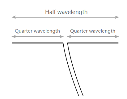
# Basic half wave dipole antenna
Each leg of the dipole antenna is joined to the feeder, this can either be open up wire / twin feeder, or coax tin be used. Strictly speaking a balun should be used when coax or coaxial cable is used. This is because coax is what is termed an unbalanced feeder, i.eastward. the outer shield is connected to globe and the antenna is counterbalanced. However for this awarding, no noticeable degradation should be seen and the VHF FM dipole antenna should operate quite satisfactorily without ane. In this case the inner conductor of the coax is connected to one leg of the dipole and the outer conductor (braid) of the coax is connected to the other leg of the dipole antenna.

Audio and Video Solutions >More
As we already had some coax cable installed around the firm, our antenna was connected to a coax connector, and a mating version was attached to the coax cablevision. It is noting that twin feeder, such as that formed past the flex does not perform well when routed for long lengths through a business firm and indicate losses volition rise - amend to use coax as this is non affected in the same way. Notation: When installing the antenna, equally far as is possible in a roof space, the antenna should away from metallic objects every bit this will reduce the betoken levels. In item the ends of the antenna are more sensitive to nearby metal objects. Nosotros strung our antenna up in the loft or roof space. As many VHF FM stations use vertical polarisation these days, we mounted the dipole in a vertical fashion: one end attached to a convenient blast in the wooden constriction of the roof, and the other end held downward by a weight. The coax was lead abroad at right angles - as much as y'all can in these circumstances!
<< Dorsum
How to Make An FM Dipole Antenna Design?
To brand an FM dipole antenna design, you need to pay attention to the details of simple to construct DIY FM dipole antenna design that tin exist congenital hands and used for indoor reception of circulate FM signals.
Ane area in which dipole antennas are often used is for the reception of VHF FM broadcasts. Many Hello-Fi tuners and other radios have input sockets that will accept the input from a coaxial feeder, and where no external antenna is used, a dipole antenna tin provide an splendid solution. Information technology is quite easy to make a simple DIY FM dipole antenna. They can be made in a variety of means and for minimal toll. They may testify to be the ideal solution for an internal FM antenna, perchance in the attic or roof space, or they may be used when a temporary antenna is needed. 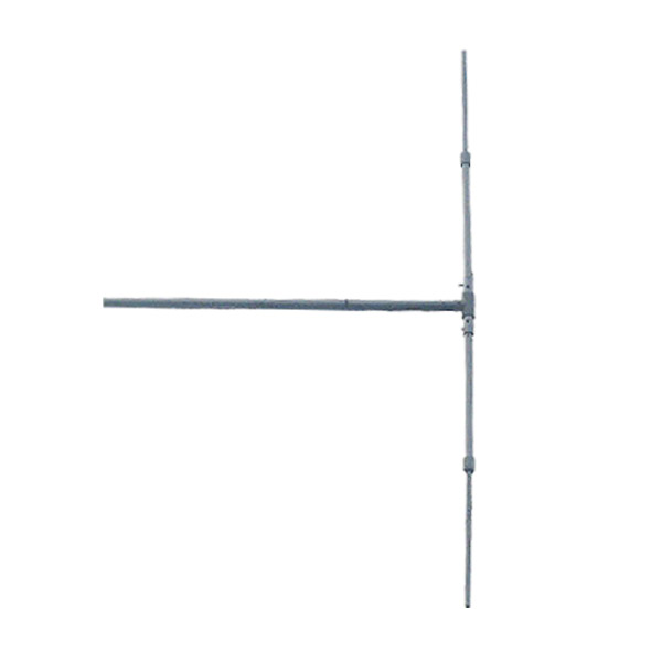 The FM dipole antenna is most probable to provide greatly improved reception over many other improvised solutions that may be used.
If they are to be used for internal use, and then in that location is no need to employ expensive materials to ensure they are not afflicted by the weather. Instead of internal apply, the DIY VHF FM dipole tin can exist made from commonly available materials and therefore the price is likely to be minimal. It may fifty-fifty be possible to make a simple FM dipole using items that may already be in a junk box, or in a workshop or garage.
Why Do Y'all Demand To Make An FM Antenna From Speaker Wire?
FM radio receivers demand an antenna to catch the FM signal that is sent from the FM radio station. Every FM station has a very weak range of supply. Usually, the range of the covered distance is about 70 miles. So, if the radio receiver is any further than that fifty Miles the FM can't accomplish the receiver very well. IN that case, a radio antenna is required. You can make an FM antenna out of a speaker wire also.
Warning:
● If your antenna is placed outside, you lot should implement some form of lightning protection.
● Antennae that are placed outdoors should take weatherproofing measures (due east.yard., waterproof blanket) in place.
Tips:
● Both antennae synthetic hither are "balanced" and volition exist inconvenient to connect to the typical "unbalanced" telescoping antenna.
● Coaxial cables and speaker wire are both adequately cheap. If you lot already have the proper tools to create your preferred antenna, yous tin make an antenna for a fraction of the price of purchasing a new FM antenna.
<< Dorsum
Simple DIY FM Dipole Antenna Pattern
To make the uncomplicated DIY FM dipole antenna, but a few items are needed. Typically these will be:
● Twin flex - twin mains flex is idea but we used some old speaker flex.
● Necktie wrap - to secure the centre of the dipole and prevent the flex opening out beyond what is needed.
● String or twine to secure the ends of the dipole to relevant fixing points (if required).
● Connectors - if it is to exist connected to coaxial cable.
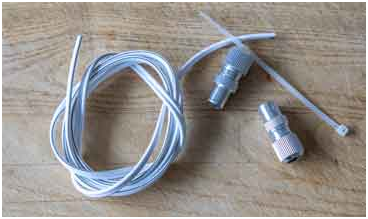
# Components required to make an FM dipole antenna
1 advantage of using mains flex is that when used as a feeder for radio frequency signals this type of wire is a reasonably shut approximation to 75 ohm twin or open up wire feeder. This is convenient if a reasonable length is needed. For making our FM dipole antenna, we used some cheap speaker wire.
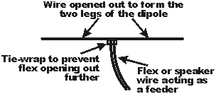
# FM dipole fabricated from twin flex
To brand up the VHF FM dipole antenna, kickoff the cable should take the 2 insulated wires divide back away from ane another and opened out. The middle should then be secured to forestall the cable opening out any further. Ane method of doing this is to employ a necktie wrap such equally those available from virtually electronics components stockists. The length of wire which has not been split can then be used every bit the feeder for the antenna.
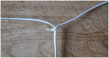
# A necktie wrap can exist used to secure the centre point of the FM dipole antenna
The overall length for the antenna should be nigh 150 cms, i.east. each leg should be 75 cms. This length should make the resonant frequency fall slightly in the lower half of the FM broadcast ring, but oft the more popular stations may be found in this region. If the resonant frequency is required to be higher then the antenna can be shortened slightly.
It is quite easy to calculate the length from one of the post-obit equations:

length (metres)=150 Aflength (metres)=150 Af
length (inches)=5905 Aflength (inches)=5905 Af
Sometimes the equations vary a petty in the constants used, as this depends on a variety of factors including the wire used, environment, frequency and the like. Still it is a very good starting betoken and certainly practiced enough for making the FM dipole antenna.

FM Circulate Solutions >More
The ends of the wire can be knotted as shown to enable it to be attached to some twine or string to set it upwards on a loft space, etc. If this is done, the length should be taken to the extremity of the wire and any wire that is part of the knot or doubled back should non be included in the length. The knotting of the wire will add together some inductance to the end of the wire, possibly making information technology a picayune long, simply information technology should exist fine for reception.
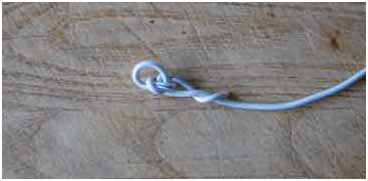
# The wire cease of the FM dipole is knotted
<< Back
The Fastest FM Homemade Antenna DIY Method for Beginners (T hree Steps Only )
▼ Step ane. A Basic Dipole Antenn a
Note: A good place to start when making an FM antenna is with a 100-foot whorl of 300-ohm dipole wire. This tin be constitute at almost any audio store and virtually department stores that carry audio electronics and supplies.
You will exist amalgam a T-shaped antenna that will attach to your wall as high every bit possible. The top section should be at least three feet long, but an ideal length would be virtually 15 anxiety.
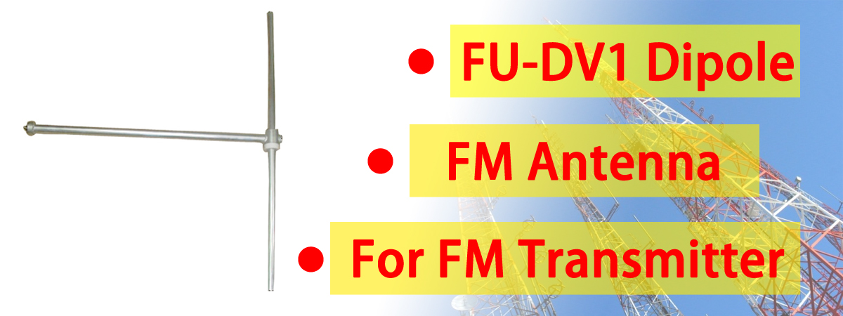
FM Antenna in Stock : FU-DV1 FM Radio Antenna . >More than
Cut the ends of the superlative section and bare the wires on each side. Twist them together and attach this length to your wall.
In the center of your top section, make a cut in the lower wire of the dipole and strip the coating from each side. You volition have two bare wires pointing down.
Cut another slice of dipole wire, blank the ends on both sides, and adhere one cease to the wires pointing down from the top section. Attach the other bared wires onto the antenna ports from your stereo. You basic dipole antenna is complete .
▼ Pace two. A Better Dipole Antenn a
 Annotation: Y'all will need to construct a simple X frame out of wood, binding the centers together, with each piece measuring 42.iv inches as an platonic length.
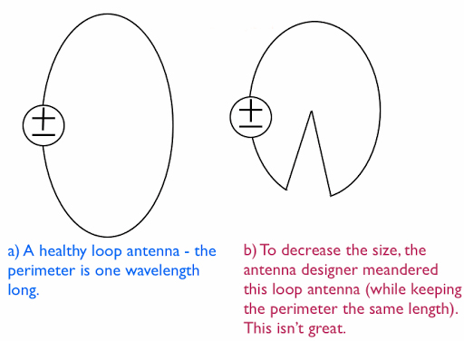
The dipole wire needs to be split in the center, then attached to the frame going in opposite directions.
This process makes what is called a airtight-loop antenna , equally there are no breaks in the wire and both leads are attached to the antenna ports on the back of the stereo.
The advantage of this design is that the antenna with supporting frame tin be moved around a room to gain best reception.
▼ Step 3. Using What'southward Available
Note: FM stereo and regular television signals run very shut to the aforementioned frequency.
Any TV rabbit ear antenna too can exist used as a basic FM antenna. To that end, any roof mounted Tv set antenna as well tin can be used as an FM antenna. You may have to cutting and strip the wire, simply you lot besides will proceeds superior FM betoken performance .
<< Dorsum
Advanced Version of FM Antenna DIY Methods (Applied as well)
Getting the appropriate betoken from a radio station turns into a claiming while you are at a considerable distance from the station. In that case, you cannot but get through some additional procedures to ensure a insufficiently better connectedness.
And so making an FM antenna will be i of the best culling solutions. But in this state, one new challenge will appear to y'all. The claiming is cipher but the making of an FM antenna in hope without the help of a technician .
You tin follow several methods to make an FM antenna in the home. Merely among them, the most prominent and easiest will be to make an FM antenna from the speaker wire. It'll be the most economical and save your time the nigh. Besides, provide you the maximum benefit. You lot can practice it by following some very elementary steps.
Then, here I will give y'all more quick tips on how you can DIY bootleg FM antenna. Follow these and get the best point in the best way.
| Method 1 | Using a Coaxial Cable |
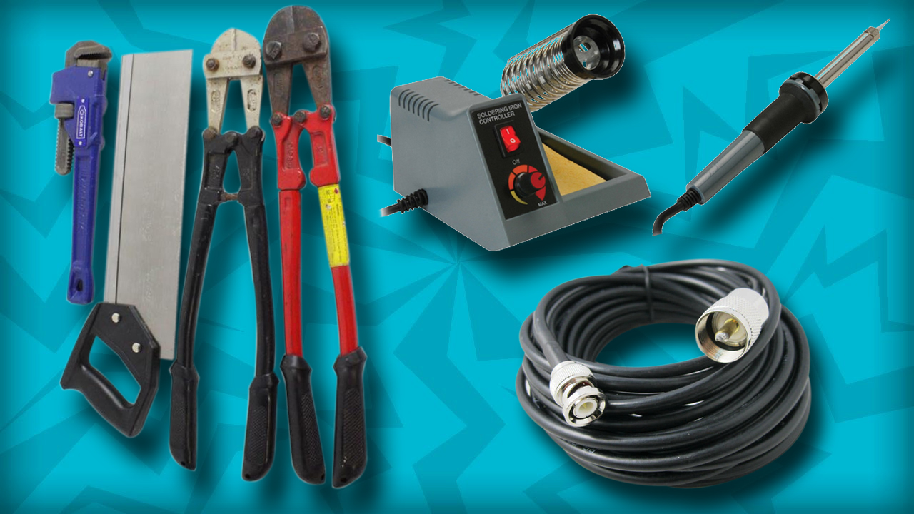 | |
▼ Step 1. Gather the necessary materials
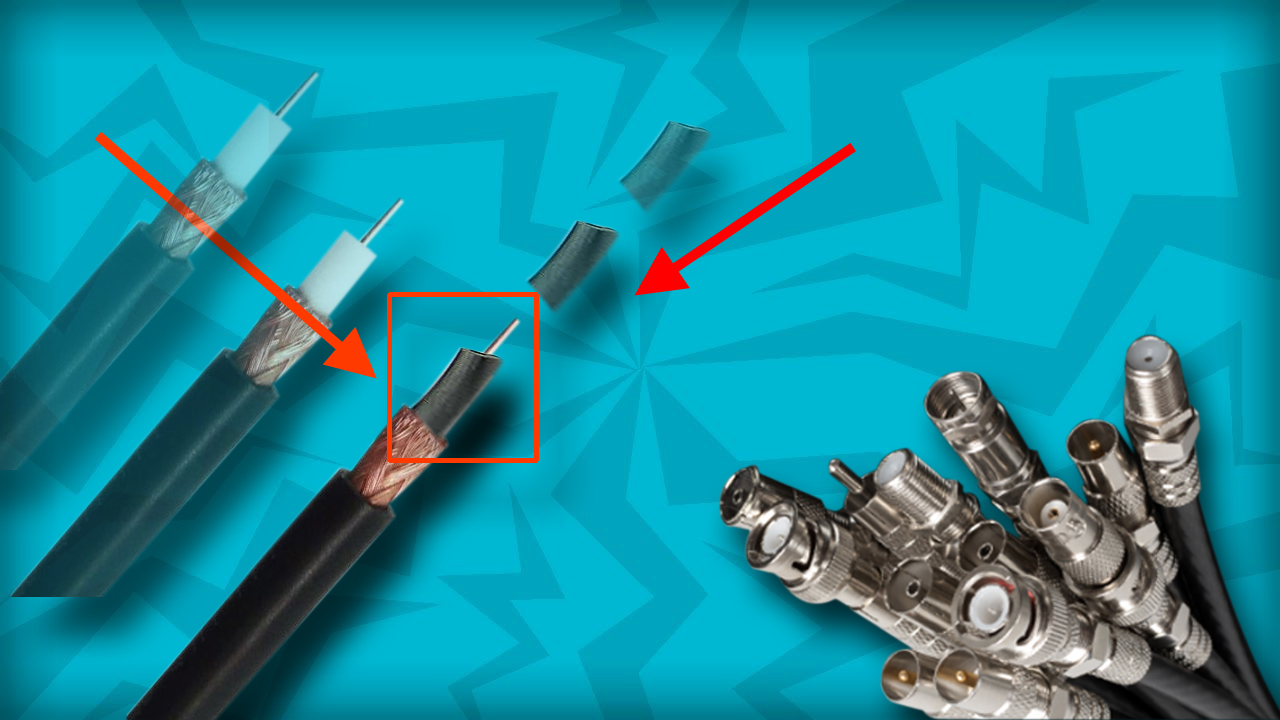
Note: In guild to make a vertical antenna from a coaxial cable , y'all will demand the following materials:
● fifty ohm (or 75 ohm) coaxial wire with copper shielding
● FM receiver with a coaxial connector
● 3/8-inch copper tubing
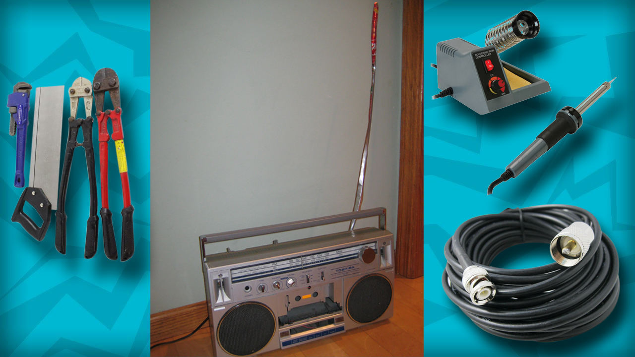
● Wire cutters
● Hacksaw
● Soldering equipment

▼ Step 2. Calculate the length of your antenna
Note: This will determine both how much of the coaxial cable you have to strip and how long your copper tubing should exist:
● Divide 468 by the frequency to which you want to connect (e.m., 468/108MHz would become 4.3).
● Divide the resulting number by 2 (e.1000., 4.3/2 would get 2.xv).
● Multiply the resulting number by 12 inches (30.5 cm) to find the antenna length (eastward.g., 2.fifteen*12 inches would become 25.8 inches).

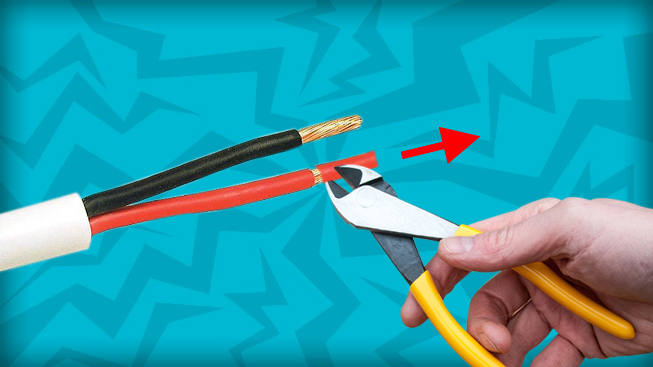
▼ Pace 3. Cut off 1 finish of the coaxial cable
Note: While yous'll want to leave 1 finish of the coaxial cable intact in order for it to serve every bit the connector, the other end will need to exist removed.
● You can use your wire cutters or a hacksaw to do this.
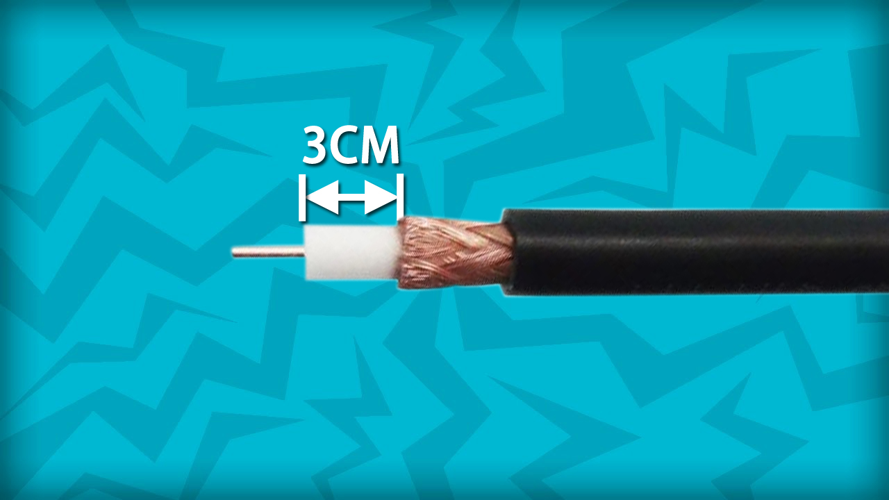
▼ Step four. Strip one-half of the antenna'south overall length from the end of the coaxial cablevision
Note: You'll need to remove each layer of shielding until you lot arrive at the white layer surrounding the coaxial cablevision itself.
| ● For case, if your antenna is supposed to be six inches per your calculations, y'all'll remove iii inches of shielding. |
| ● Y'all'll need to remove the copper shielding during this process. The easiest way to do so is past making a shallow incision with the hacksaw all the way around the shielding and then attempting to strip it off from there. |
▼ Step 5. Cut the copper tubing to half of the antenna'southward overall length
Note: The copper tubing will comprise the other half of your antenna'due south receiver, so information technology should be the same length as the section that you just stripped.
● Once more, if you lot're using a six-inch antenna, the copper tubing will be iii inches.
▼ Pace half-dozen. Cutting the copper tubing to half of the antenna's overall length
Note: Attach the tube to the coaxial cable. Slide the copper tubing onto the coaxial cablevision'due south stripped terminate, then slide it down to the bottom.
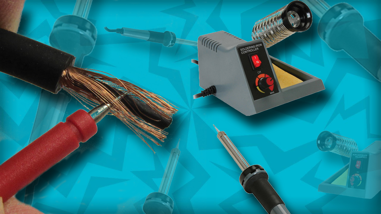
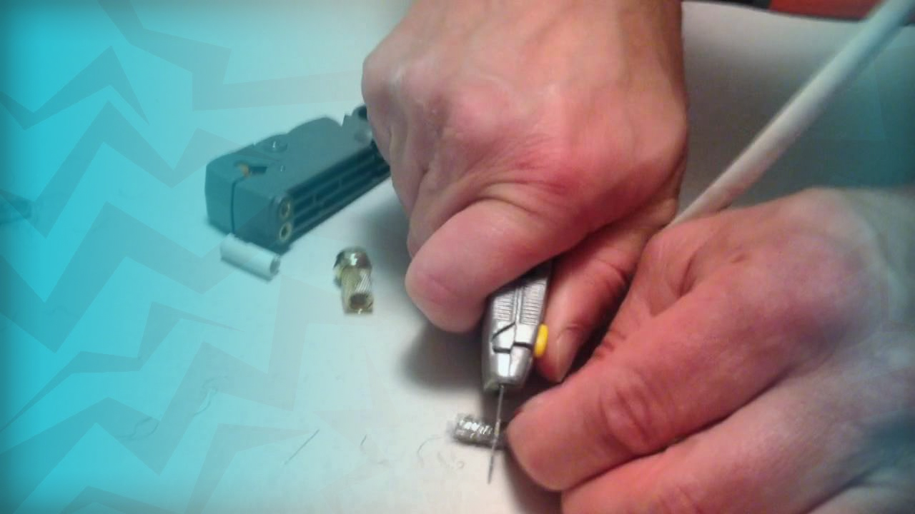
▼ Pace vii. Solder the coaxial cablevision'south shielding to the tubing
Notation: You tin exercise this past removing the PVC (blackness) shielding from effectually an inch of the coaxial cable directly below the unshielded function, peeling it back with a pair of pliers to form a lip, and and so using your soldering pen to connect the lip to the copper tubing.
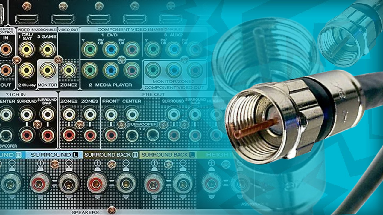
▼ Stride 8. Connect the coaxial cable to your audio receiver
Notation: The remaining coaxial connector should plug into the receiver's coaxial antenna port, which makes the balance of the antenna placement adequately simple.
▼ Stride ix. Place the antenna
Note: Once the antenna is plugged in, angle information technology toward the nearest station and secure information technology in place if necessary.
● The fewer obstructions between your antenna and the nearest FM station, the stronger your betoken volition be.
● Your coaxial cable may be strong enough to stand on its own without needing support, merely you can use stables or any adhesive to prop upwardly your antenna as needed.
<< Dorsum
| Method two | Using Speaker Wire |
 | |
▼ Stride i. Understand when to use this method
Note: If your connectedness to an FM station is mostly fine simply requires some fine-tuning from time to fourth dimension, yous can utilise speaker wire as a quick range-extender to amend the quality of your connexion.
● Speaker wire is not an ideal solution to long-range issues. If y'all're having problem receiving a bespeak at all, you lot should effort using coaxial cable instead.
▼ Pace two. Assemble the necessary materials
Note: In order to arts and crafts a crude antenna from speaker wire, you'll demand the following items:
● 10 anxiety of speaker wire
● FM receiver with clamp-and-hold (or mail) FM connections
● Wire strippers
▼ Step three. Split three feet of the speaker wire
Note: You should exist left with 3 feet of spit wire and vii anxiety of intact wire.
● Using a knife or a pair of pliers, split the top three feet of the speaker wire tubes from each other.
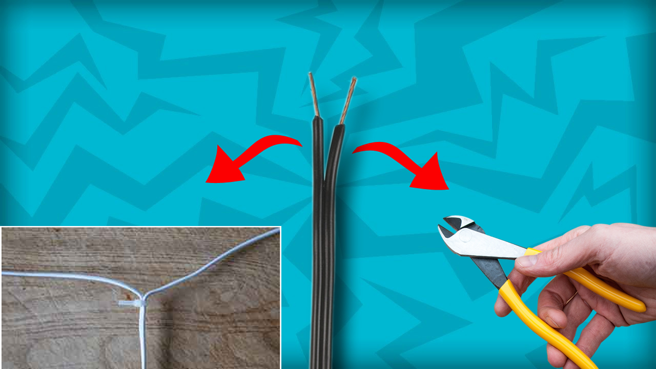
▼ Step 4. Carve up iii feet of the speaker wire
● Arrange the speaker wire to class a "T" shape. You'll do this by bending each of the split wire ends at a xc-degree angle to the vii-human foot department of wire.
▼ Step five. Strip the bottom two inches of insulation from the speaker wire
● Use the wire strippers to practice then. This volition betrayal ii bare wires at the lesser of the "T" shape.
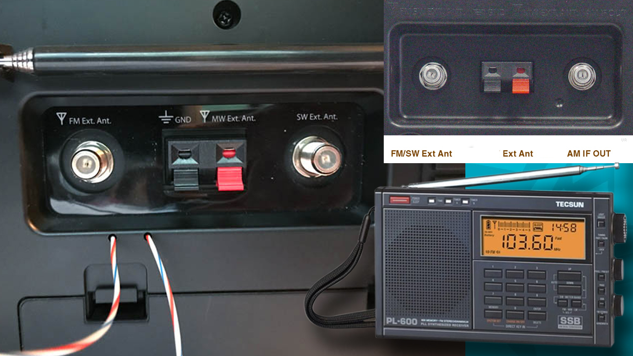
▼ Step half dozen. Find your receiver's antenna connections
Note: These two connections will normally be marked "FM EXT" or "ANT EXT", but yous'll almost always encounter "FM" somewhere nigh the connectedness; you should also run into the word "Balanced" or "BAL" most the appropriate connections.
● FM receivers can have either clamp-and-hold connectors or post connectors. Clench-and-hold connectors resemble literal clamps, while post connectors resemble knobs with exposed metal between them and the receiver itself.
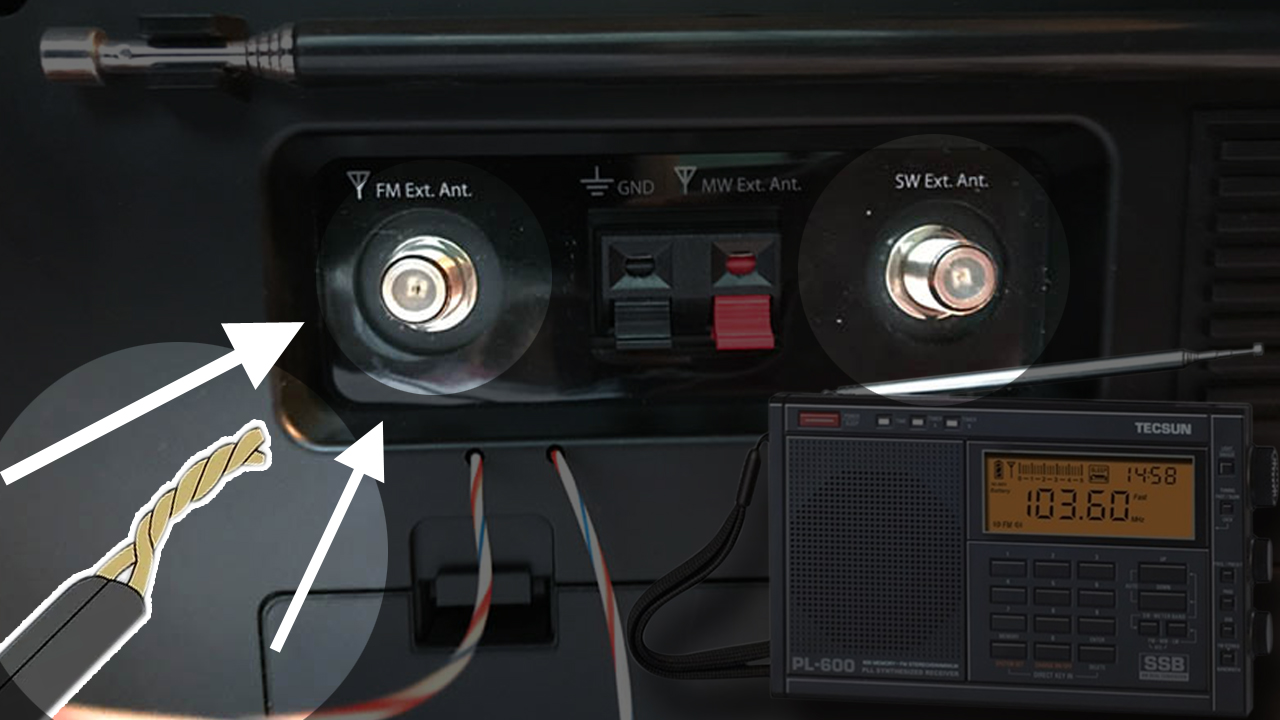
▼ Step 7. Connect the bottom of the "T" to the receiver
Note: If there's just 1 FM connection, you lot can twist the two bare wires at the bottom of the "T" together to grade one wire that tin connect to the clench or post.
● Utilize each of the exposed wires at the bottom of the "T" shape to connect to each of the FM connections.

▼ Footstep 8. Place the antenna
● Ideally, you'll place your antenna every bit high upward and equally close to the nearest station equally possible. In some cases, this may mean threading your antenna forth the pinnacle of a wall, or even running it outside.
Notation: You lot may take to move the FM receiver in order to make this possible.
<< Dorsum
In Decision
Stride 1 (CHOOSING THE WIRE AND MARKING IN Information technology)
At first, you need to take a ten anxiety length of dual speaker wire. Then mark up to the iii anxiety distance. Now carve up the dual speaker wire and create a T shape. This means the 3 anxiety portion will exist perpendicular to the balance 7 feet.
Now you have to strip the 2 inches of the finish of the insulation layer from the wire. Now y'all need to connect the wire with the speaker. Now observe the external connexion pigsty if the speaker may be labeled as "ext" or "emmet." After information technology, yous should wrap the post of the speaker, and then if the speaker is a clamp and concur so you should clamp and hold.
STEP two (CONNECTING TO THE Concord OR CLAMP)
Subsequently twisting the wires together into the single wire, it is necessary to put the connection if the external antennae connectedness is a single postal service or clamp.
STEP three (EXTENDING THE ANTENNA FOR THEM TO Accommodate THE All-time SUITABLE POSITION)
Now I will guide y'all to extend the antennae. Now you have to put the receiver near a window. On the exterior of the window, you take placed the wire in every bit much loftier a position as possible. Now yous have to extend the wires in opposite directions of the window in ii different directions.
STEP 4 (GETTING THE PERFECT Adjustment OF THE RECEIVER)
Afterward that, information technology is necessary to check the reception of the receiver. Switch the receiver on and check the signal level of the expected channels. You can relocate the wire to the opposite directional window check the bachelor signal level if you are non satisfied with the kickoff i. So you lot should extend some end part of the wire if you all the same don't get the expected result.
STEP 5 (ADDING THE LENGTH FOR Ameliorate Betoken)
Adding the length to the antenna lead may also be required. For that, it is very much necessary to add together the length to get more betoken level. To practice that cut the length of the speaker wire. Separate the two wires into two different wires.
At present strip the insulation layer from one end of whatever of each of the long wire. Strip 1 cease of insulation from the antennae leads. At present twist the exposed parts of the ii-unlike end of both the wires that means twist the exposed part of the wire to an extension to one antenna atomic number 82.
Repeat this step on the other leaders also. Now you tin can extend the full length of both longer leads again. Then you lot may likewise demand to back up a finishing smash if it is required.
With this method, you can be able to make an FM antenna out of the speaker wire. This is the method of making the FM antennae in piece of cake steps. You should follow the steps that I take suggested every bit precisely as possible. Bask meliorate and quicker signal.
<< BACK
How To Brand A VHF FM Folded Dipole Antenna?
Many VHF FM hi-fi tuners have a 300 ohm input also as the standard 75 ohm ane. This input will normally take screw terminals although they will sometimes have a special 300 ohm connector. This input is ideal for employ with a VHF FM folded dipole antenna which tin be made up very simply. Information technology requires only the use of a length of 300 ohm ribbon cable (not the computer multi-stranded ribbon cable) which tin be bought from most electronic component stockists.
The offset stage is to cutting a length slightly longer than that required for the dipole chemical element. At either cease the centre plastic should exist cut back and the remaining wire on either side stripped and joined together. This should be done making sure that the overall length of the element is correct.
The next stage is to cut the bottom wire in the centre. The wires should exist stripped dorsum so that a 2d length of ribbon can exist fastened. This can be made any suitable length, bearing in heed that information technology is likely to introduce a reasonable amount of loss if it is run inside the house close to other objects. This enables the 300 ribbon to be used as feeder to be connected. This may be any suitable length.
This cheap and easy VHF FM dipole antenna is suitable for areas with high signal strengths, or information technology may be used as a temporary measure. The 300 ribbon cablevision is generally clear and can be hidden quite hands. Often this type of aeriform can be fixed behind a pall runway or a large article of furniture.
Annotation: A dipole antenna is often an platonic solution for an antenna for receiving VHF FM broadcasts. The FM dipole antenna tin can exist a cheap and effective solution, and they can be fabricated in a multifariousness of forms - only two ideas are given above, but it is possible to make a VHF FM dipole antenna in many more ways according to what may be available and what the requirements are.
<< BACK
How to Make a Uncomplicated Antenna to Improve the Reception of an FM Radio Receiver
FM radio reception depends on distance between your receiver and the transmitting belfry. A receiver with no antenna attached receives the strongest signals, but these may be decumbent to interference and drifting signals. A uncomplicated antenna not but stabilizes the betoken from the strong stations, it allows your receiver to recognize stations with less powerful transmitters and at greater distances. A dipole antenna is simple in configuration and uses inexpensive materials in construction. Mounting such an antenna outdoors improves its effectiveness.
Step one
Measure 28-3/iv inches from one end of your wire. Wrap several turns of electrical record at that point. This represents a quarter-wavelength tuned to the heart of the FM radio band.
Step two
Split the wire from the terminate to the tape. Spread the wires in contrary directions. These are the ii poles of your dipole antenna. Use the wire strippers to remove 1/2-inch of insulation from the contrary finish of your antenna and twist the exposed ends to prevent fraying.
Pace 3
Attach each exposed end to one of two screw terminals on your receiver marked for the FM antenna. Loosen both screws, past hand or with a screwdriver, depending on your receiver. Wrap the exposed wires around the screw threads and tighten. Information technology doesn't matter which wire is connected to each terminal.
Extend and adjust the poles of your antenna to obtain the all-time results. The dipole antenna is directional, so changing its location and orientation volition bear upon reception. Individual stations will be affected differently. Apply hardware or additional tape to improvise support for your antenna.
<< BACK
How to Get More Channels With A Bootleg Antenna?
Cable and satellite idiot box provides yous with an almost endless multifariousness of shows, simply as service providers raise prices and cut channels, you may decide to return to basic TV. Y'all don't have to settle for just one or two channels with bones television receiver. Making your own bootleg Television receiver antenna allows you to selection up on channels previously unavailable to you. The antenna also boosts your tv's signal, so you run across and hear your favorite shows more clearly.
Step 1
Bend each 17-inch copper wire in half to form viii pairs of ears. Spread the ear tips three inches apart.
Step ii
Put a slice of oestrus-shrink tubing over the end of each ear tip. Shrink the tubing with a heat gun.
Step 3
Saw the 38-inch pine board into two pieces, a vi-inch piece and a 32-inch piece. Place the 32-inch pine board flat on the floor or table. Adjust four pairs of ears on each side of the board, with the tips of the ears facing outward. Thread the two 34-inch copper phasing bars through the ears as if lacing a shoe.
Step 4
Put one washer over the eye of each pair of ears. Use a drill to secure the washers with screws.
Step five
Wrap a small piece of electrical tape over the intersecting stage confined. The electrical tape prevents contact betwixt the bars.
Pace 6
Drill ii washer and screws next to each other in the centre of the lath. Wrap the ends of the impedance-matching transformer (IMT) around the washers.
Stride vii
Use two fibroid-threaded screws to attach the 32-inch pine board to the 6-inch pino board, forming a base for the antenna.
Footstep 8
Connect a coaxial cable to the end of the IMT. Connect the other end of the cable to your idiot box's converter box. If you lot have a digital-ready television, connect the coaxial cable directly to the TV instead.
Note: Adapt the antenna until you pick up channels. Make further adjustments to get the all-time-quality movie.
<< Back
How to Build a Bootleg Radio That Really Works
Prophylactic FIRST: Enquire an adult to assistance with tools yous haven't used before.
Radios might seem super high-tech. But with well-nigh $fifteen and 1 afternoon, y'all can make one at home.
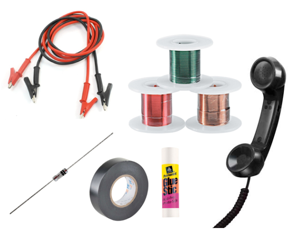
▼ WHAT Yous'LL Demand
● Magnet wire: Electronics supply stores often sell a ready, for about $10, that comes with xl feet of 22-gauge, 75 anxiety of 26-gauge and 200 feet of 30-gauge magnet wire.
● one set of alligator leads with clips at each cease.
● 1 diode: Look for IN34A diodes, also chosen "germanium diodes," at an electronics supply store or online.
● 1 glue stick or anything similar in size — most i inch by 1 inch by 6 inches. Information technology can be a piece of woods. It doesn't have to be perfectly round, but using something round is easier for winding.
● Electrical record
● Wire stripping pliers
● Telephone handset with cord. If you don't accept an one-time telephone that you don't use anymore, yous might be able to find one at thrift stores or garage sales.
● One board for mounting your radio — 2 feet past two feet volition work. Yous can make the radio without this, simply having a workspace and a place to mount the radio makes it easier to carry around while you're looking for a place to hook the ground wire.
▼ WHAT YOU'LL Practise
Pace 1:
Wind 26-gauge wire (the light-green magnet wire) around the glue stick until it covers near the entire cylinder. Proceed the wire tight. Get out about six inches of wire on each end. Once you lot're finished winding it, record around both ends of the cylinder to make sure the wire holds. Then, mount the coil to the lath with electrical tape.
Stride 2:
Strip the ends of the wire you've left from each terminate of the coil. Utilize wire stripping pliers or sandpaper. The wire is very thin. Removing the enamel and exposing nearly one inch of the wire should be easy.
Footstep 3:
Adhere the wire from the right side of the whorl to one cease of your diode. Record the connection.
Step 4:
Cut the end of the telephone cord and strip about ii inches of information technology. It should betrayal two wires. Strip those wires. Take your time; this wire is thin. (Try this tip: Earlier hooking up the tiny telephone cord wires, become some thicker insulated magnet wire and record about two inches to each wire. This will brand the rest of the task easier.) Attach 1 end of the wire to the exposed end of the diode. Tape that connectedness.
If your phone cord has four wires instead of two, yous take to figure out which two volition work. Take a 9-volt battery and identify ane cord against the positive (+) pole of the battery and another cord on the negative (-). When you lot find a combination that makes a clicking sound in the headset, you lot have found the 2 wires to utilise.
Step 5:
Connect the second telephone wire to the green wire coming from the left side of the coil. Before taping this connection, clip one of the alligator leads to it. Tape those three wires together — the alligator lead (that'southward your ground wire), the telephone wire and the wire coming from the left side of the coil.
Stride 6:
Make your antenna past clipping one of the remaining alligator pb wires to one stop of the 22-judge magnet wire. Exit this wire on its roll.
Footstep vii:
Scrape a thin strip of enamel from the wire wrapped around the glue stick. Y'all can practice this with any sharp object or a piece of sandpaper.
<< Back

>More
▼ SEE IF Information technology WORKS
● Attach your phone cord to its handset.
● Discover a good ground for the alligator wire that's connected to the left side of your coil. A pipe going into the ground is perfect.
● Unroll the antenna wire and hang it over a tree branch with help from an developed.
● Touch the alligator prune that leads to your antenna wire to the tiptop of the gyre. Y'all should be able to hear an AM radio betoken.
▼ TROUBLESHOOTING
● If you lot can't become any betoken, it'southward probably your ground wire. With permission from an adult, unscrew one bolt that holds the faceplate to a lite switch or outlet. Unscrew it just enough to hook your alligator prune. Don't remove the plate.
● If you go a weak signal, it'southward your antenna. If your parents have an old television antenna, hook your radio antenna wire to one of the connections on the TV antenna wire instead of running wire up a tree.
Last Words
FM radio antenna DIY may be difficult, simply please keep in heed, as long as you prepare all the production materials we mentioned, and follow the method provided by FMUSER to DIY FM antenna, y'all are a successful amateur FM radio fan!
There is nothing more heady than making an FM radio antenna by yourself. If you see any difficulties in making an FM antenna, please consult FMUSER! Have a nice day!
<< BACK
For more homemade antenna info delight contact me in Web | App
Whatsapp +8618319244009

Or Contact me by sending Emails| Mail Us
[email protected]

Leave a message
Message List

Source: https://www.fmuser.net/content/?856.html
Posted by: perezscre1994.blogspot.com
0 Response to "How To Make A Fm Radio"
Post a Comment